Domestic and industrial loads contain increasing numbers of electronic circuits that are supplied with currents that are not purely sinusoidal. For example, engines increasingly use frequency regulation, which requires converting alternating current (AC) to direct current (DC) and then DC back to AC. Given that the supply is normally in AC, this requires increasing use of electronic power converters (rectifiers, inverters, etc.) for these DC-AC and AC-DC transformations. The same thing happens with common loads like computers, LED and discharge lighting, lifts, etc.
This means that the electrical network must supply a large number of charges that rectify the current, distorting the wave shape of the current being consumed so that it is not a purely sinusoidal wave but rather a superposition of sinusoidal waves with frequencies that are multiples of the network frequency (harmonics). Figures 1 and 2 show the typical consumptions of one network with single-phase rectifiers and one with three-phase rectifiers. This type of current is most abundant in installations like offices, shopping centres, hospitals, etc., and it is formed by a 50 or 60 Hz component (network fundamental frequency) and a set of different percentages of components with multiple frequencies. These percentages may be measured using a harmonics analyzer, which can also measure the total distortion rate, or THD, which gives the ratio between the effective value of the ripple and the effective value of the fundamental component.

|
The result of non-sinusoidal consumption is that the voltage also suffers some distortion due to the voltage drops in the impedances of lines and transformers. In the logs we can note a slight voltage distortion in the single-phase network (low THD) and a stronger distortion in the three-phase example. In both cases the current shape differs greatly from the sinusoidal current, and the THD values are higher. To regulate this issue and limit the voltage distortion levels at connection points to public networks, there are international standards that establish harmonic emission limits for units and systems connected to the network (Table 1). The most significant are those associated with compatibility levels. |

We can better understand harmonics problems by looking at some basic concepts which have been published in several articles and books, and which are summarised below:
In short, the solution to the harmonics problem is two-pronged: On the one hand, users must limit the number of harmonic currents generated by their receivers and must try to distribute electricity in their plants with low impedance per metre of cable. On the other hand, the distribution company must ensure minimal short-circuit power and must ensure that users do not exceed certain distortion limits, so as not to cause harm to their neighbours sharing the network.
When the harmonic levels generated by receivers are not permitted for the distribution system supplying them, corrective filters must be installed. In this article we are going to focus on explaining the concept of filtering.
Compatibility limits due to harmonicsThe presence of harmonics in a network has several consequences. The most significant are described below.
To avoid these issues, there are standards that establish a minimum power quality which limits the maximum distortion levels for the voltage wave supplied at the connection point to the public network (PCC). These limits are called compatibility limits. Table 2 presents a summary of these limits for harmonics in industrial LV networks. The different classes mentioned in this table correspond to:
|
 in industrial LV networks (IEC-61000-2-4)")
|
Voltage harmonics are due to the voltage drop produced by current harmonics on distribution line impedances. This is illustrated in Fig. 2. So, reaching these limits depends on two factors:
")
Table 3 gives the emission limits for low voltage networks established by the EN-IEC-61000-3-4 standard for mains connection at which the installed power in the disturbing elements does not exceed (33xScc), where Scc is the short-circuit power corresponding to the mains connection (Proportional share of the total short-circuit power of the contracted power).

Some of the disturbances mentioned above can be mitigated and corrected through filters. Active filters are the perfect solution for installations with a large number of single-phase and three-phase loads that generate harmonics and that have different consumption regimens.
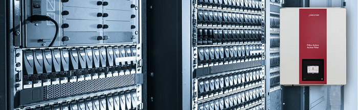
Active filters are units based on transducers that modulate the PWM pulse width. There are two kinds: Serial filters and parallel filters. Parallel filters are often used to comply with the IEC-61000-3.4 and IEEE-519 standards, as they are based on using an inverter to inject the harmonics consumed by the load into the network in anti-phase. Fig. 3 illustrates this operating principle, showing the load, filter and network currents. We can see that the sum of ILOAD + IFILTER gives us a sinusoidal INETWORK current. Fig. 4 shows a parallel active filter and its schematic diagram.


BaoGang Road, No.263(510240)
HaiZhu District (GuangZhou) CHINA
Tel: (+86) 020-84395068
Fax: (+86) 020-84390828
E-mail: Sales@circutor-cn.com

版权所有:萨科特电气 粤ICP备16000179号